


Conformation of Pressure-Sensitive Film to Complex Three-Dimensional Interfaces
Surry, K.J.M.*, Liggins, A.B.+ and Finlay, J.B.++
* Imaging Research Laboratories, Robarts Research Institute, London, Ontario, Canada.
+ Department of Orthopaedic Surgery, Temple University, Philadelphia, Pennsylvania, USA.
++ Trudell Medical International, London, Ontario, Canada.
Introduction
Contact areas and interface pressures have been used to investigate normal joint function[1], examine the effects of pathological changes[1], assess the function of prosthetic replacements[2] and study post-surgical function[3].
The most popular pressure/contact area transducers feature a thin sheet (or sheets), placed between the contacting surfaces: their output may be a single image of maximum pressures/contact areas[4], or a dynamic image of pressure/contact areas during loading[5].
Fuji Prescale pressure-sensitive film (Fuji Photo Film Co. Ltd, Tokyo, Japan) is arguably the transducer of choice in biomechanics. This sheet-based medium uses a chemicalrelease mechanism to produce a pink stain: a greater pressure generates a darker stain[6]. A relationship between applied pressure and stain-density can be determined, allowing full field pressure-maps to be generated[6].
Biomechanical joint-interfaces (physiological, pathological and prosthetic) can be small, and can contain complex three-dimensional surfaces. Hence, a sheet-based transducer may ’┐Įcrinkle’┐Į, due to an inability to conform to the surfaces; this effect can create both pressure and contact area artifacts[7].
Artifact Removal
An image processing technique for removing crinkle artifact from a digital Fuji film stainimage has been described[8]. However, it has been shown that crinkling may cause the film to interfere with the joint interface, such that true contact areas may fail to register[7]. Such findings cast doubt on the ability of image processing techniques to provide adequate artifact-compensation.
A mechanical solution is to cut the film into a shape, or shapes, that will conform to the surface. An early method was to cut small circles of Fuji film and place them over a joint surface[4]; however, this approach results in a loss of coverage across the surface and the potential loss of significant data.
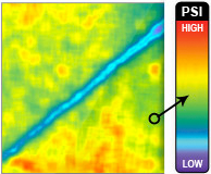
Petal-shaped cut-outs have been used on the spherical femoral head[9]. Figure 1a shows such a cut-out, on a simulated prosthetic femoral head. Here, the petals connected at a single focal point; their shape was developed from simple geometry. Figure 1b shows the subsequent Fuji film stain.
For more geometrically-complex, surfaces, a simple cut-out has been shown to regain the true contact areas that were previously lost to crinkle artifact[7].
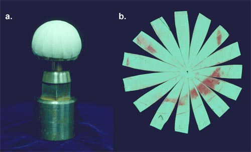
Figure 1. Fuji film cut-out (a) and resulting pressure-stain (b) for a spherical surface.
Objective
The objective of this work was to develop a standardized, optimal, technique for producing cut-out shapes for complex surfaces and to examine the practical considerations necessary for its implementation.
The trial-surface for this study would be that of the patella component of a total knee replacement.
Patellar Component Surface Contours
The ultra high molecular weight polyethylene (UHMWPE) patellar component (Figure 2a) was designed to articulate against a metallic femoral component. The ’┐Įsaddle-shaped’┐Į articulating surfaces consisted of a uni-planar central section with concave medial and lateral sections, as indicated.
A three-dimensional model of the articulating surface was created in the AutoCad environment (AutoDesk Inc., Sausalito, CA). AutoCad’┐Įs three-dimensional modeling routines were then used to sequentially cut slices (at 0.5mm spacing) through the surface (Figure 2b): the slice-outlines, projected onto a single plane, produced a contour map of the surface (Figure 2c).
Two distinct groups of contours (1 and 2) were clearly identified. Between these groups were a pair of delineating ’┐Įborder-contours’┐Į (3).
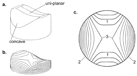
Figure 2. Patellar component (a) and surface contours (b,c).
Cut-out Development
For any cut-out, there are four main considerations: determination of an attachment point(s) for the petals; location of the focal point(s) for petal-cutting; petal-shape development; and petal-overlap elimination.
Petal Attachment
A strip of film lying over the uniplanar section of the patellar component will not crinkle (as it will bend in one dimension only). Therefore, an area of the cut-out corresponding to the uniplanar section (Figure 2a) provided a suitable base for the cut-out and an attachment point for the petals.
For other three-dimensional surfaces, such uniplanar sections can be determined by the presence of sets of straight, parallel, contour-lines.
Focal Point Location
Unlike sphere-geometry (Figure 1), the patellar component contours did not indicate an obvious single focal point, from which cut-lines could be radiated.
Considering the contours in groups 1 and 2 to be quasi-concentric, perpendicular lines were drawn from the endpoints of the outermost curve for each group (Figure 3a): this curve corresponded to the border-contour (3), defined above. The intersection of these perpendiculars provided four focal points (FS and FD, see explanation below) from which to radiate cut-lines, and hence develop the cut-out petals.
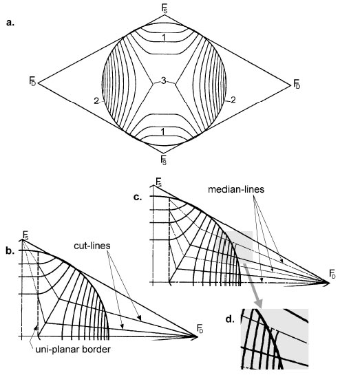
Figure 3. Determination of focal points (a), cut-lines (b), medians (c) and contour extensions (d).
Petal-Shape Development
The following development was conducted in the AutoCad environment. Symmetry was used to reduce surface analysis.
Contour-group 2 (Figure 2c) was designated as the ’┐Įdominant’┐Į group. That is, it dominated the surface and would be the main determinant for decisions regarding petal-shape development.
Cut-lines were radiated from the dominant focal point, FD, (Figure 3b) to the bordercontour. These lines were such that the resulting segments were regularly spaced. Similarly, cut-lines were radiated from the secondary focal point, FS, to intersect the bordercontour at the same points as those from FD.
The cut-lines crossing the secondary contour-group (group 1 in Figure 2c) were truncated at the border of the uniplanar section, thereby creating attachment points between this section and the subsequent petals.
A median line for each petal was radiated from FD (bisecting the cut-lines) and across both sets of contour-lines (Figure 3c), to the border of the uniplanar section. If a contour-line did not cross the median, the AutoCad ’┐ĮExtend’┐Į command was used to extend the contour to the median (Figure 3d).
Along each median (Figure 4a), the distance, dn, between each contour and the lengths of the contour-segments (lnL and LnR) between the median and the cut-lines were measured.
Using Pythagoras for the lengths of a right-angled triangle, the two-dimensional distance between contours (dn) and the height between contour-slices (0.5mm) provided the three-dimensional distance, Dn, between contours, along the surface. Hence, the positions of the contours along the median could be corrected for the three-dimensional surface (the lengths of the contours remain the same) and the petal-edges determined (Figure 4b).
Each petal-shape was determined separately and then attached to the uniplanar section, at an angle determined by the three-dimensional geometry at this point.
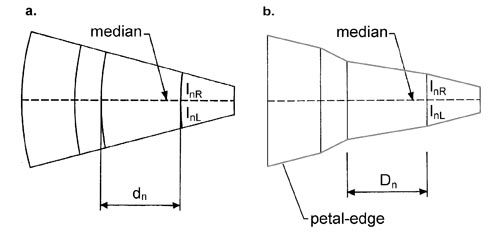
Figure 4. Petal-shape development.
Petal-Overlap Elimination
Due to surface concavity, petal-overlap was observed (Figure 5). In these cases, an alternative cutting line was determined, mid-way between the two overlapping petal-edges.
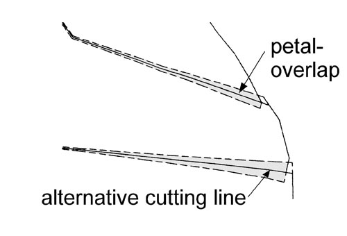
Figure 5. Petal-overlap elimination.
Output and Cutting
A flat-bed plotter, with felt-tip attachment, was used to transfer the cut-out outline to the reverse (non-active) surfaces of the Fuji film. The resulting lines were cut with a sharp scalpel. Here, care must be taken to avoid undue surface pressure, which could prematurely activate the film.
Discussion
The final cut-out shape is shown in Figure 6a. Here, tabs have been added to each end of the uniplanar surface, to aid in handling and orientation. Figure 6b shows the cut-out applied to the patellar component. Figure 6c shows a sample pressure-stain from articulation with the prosthetic femoral component. This result can be compared with Figure 6b: here uncut Fuji film was placed in the same interface, resulting in extensive crinkle-artefact. This technique was clearly developed for one particular application; however, the steps described here could be easily adapted to other complex interfaces.
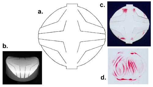
Figure 6. The cut-out shape (a), its application on the patellar component (b), the resulting pressure-stain (c) and the crinkle-artefact produced by uncut film.
References
- Fukubayashi, T. and Kurosawa, H. Acta Orthopaedica Scandinavica, 51: 871-879, 1980.
- McNamara, J.L., et al. Clinical Orthopaedics, 299: 104-113, 1994.
- Marder, R.A., et al. Journal of Bone and Joint Surgery, 75A(1): 35-45, 1993.
- Singerman, R.J., et al. Experimental Mechanics, 27(1): 99-105, 1987.
- Harris, M.L., et al. Journal of Biomechanics, 32: 951-958, 1999.
- Liggins, A.B., et al. In: Little, E.G. (Ed), Experimental mechanics: Technology transfer between high tech engineering and biomechanics. Amsterdam: Elsevier Science Publishers. 61-70, 1992.
- Liggins, A.B. In: Shelton, J.C. and Orr, J.F. (Eds), Optical measurement methods in biomechanics. London: Chapman and Hall. 174-189, 1995.
- Caldwell, N.J., et al. Journal of Biomechanics, 26(8): 1001-1009, 1993.
- Afoke, N.Y.P., et al. Journal of Bone and Joint Surgery, 69B(4): 536-541, 1987.